I'm rewiring a sewing machine.
Using the wiring from a new style foot controller that's got a bad controller to replace the spaghetti hard wire on the old one. BOTH antique and new are wired the same way.
OK, follow me if you can.
New style wire has polarized non-grounded plug. Wide plug side has white stripe on it. Narrow side is plain.
Power cord enters into a three way female plug.
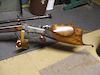
Here's a pic I just found:
The two connectors would go to the foot controller and you can see how 4 wires go into 3 prongs.
The motor and light are all run off this three way plug but are wired to the male side. The foot controller comes off the female side with the power cord.
New wire white strip side goes to the center prong of the plug. Plain side goes into outer prong on one side. White stripped wire from foot controller mates up with power cord white side in the center, plain side goes to opposite outer prong.
Now, the original cord's plug is not polarized being about 90 years old. The cord itself has been replaced who knows when. On the old cord one side has a ridge the other is plain.
It is wired opposite the new cord with the plain side to the center and the ridged sides to the outer prongs.
I'm going to use the polarized plug and simply replace the foot controller and the 3 way plug with the ones appropriate to the old sewing machine.
OK, here is the question if you've followed me this far.
Will it matter if I wire the old plug and foot controller as the new ones are wired?
I dont' "think" so since the non-polarized plug obviously doesn't care which way it's plugged in and neither did the machine.
But I'm not sure.
Anybody care to add some input here?
Joe
OT electrical question, I FIXED IT, update 2 more pix
Forum rules
Welcome to the Leverguns.Com General Discussions Forum. This is a high-class place so act respectable. We discuss most anything here other than politics... politely.
Please post political post in the new Politics forum.
Welcome to the Leverguns.Com General Discussions Forum. This is a high-class place so act respectable. We discuss most anything here other than politics... politely.
Please post political post in the new Politics forum.
-
J Miller

- Member Emeritus
- Posts: 14885
- Joined: Sat Mar 31, 2007 7:46 pm
- Location: Not in IL no more ... :)
OT electrical question, I FIXED IT, update 2 more pix
You do not have the required permissions to view the files attached to this post.
Last edited by J Miller on Sat Oct 08, 2011 10:52 pm, edited 3 times in total.
***Be sneaky, get closer, bust the cap on him when you can put the ball where it counts  .***
.***

Re: Another OT electrical question
If it were a newer device there might be some concern over which side of the circuit an internal fuse or circuit disconnect device might be wired on, and without being there with my personal multimeter, my reptile brain tells me that it would the thing to do to keep all of the wires with raised ridges, white lines, and solid white wires in the same run of wire. Otherwise, I'm thinking that since you're probably plugging it into an AC source, it ain't really gonna matter as far as the way it operates.

Last edited by FWiedner on Fri Oct 07, 2011 7:24 pm, edited 2 times in total.
Government office attracts the power-mad, yet it's people who just want to be left alone to live life on their own terms who are considered dangerous.
History teaches that it's a small window in which people can fight back before it is too dangerous to fight back.
History teaches that it's a small window in which people can fight back before it is too dangerous to fight back.
-
J Miller
- Member Emeritus
- Posts: 14885
- Joined: Sat Mar 31, 2007 7:46 pm
- Location: Not in IL no more ... :)
Re: Another OT electrical question
I was thinking the same thing, but wasn't sure. I never did understand this polarized deal anyway.FWiedner wrote:If it were a newer device there might be some concern over which side of the circuit an internal fuse or circuit disconnect device might be wired on, but without that consideration I'm thinking that since you're probably plugging it into an AC source, it ain't really gonna matter as far as the way it operates.
DC power yes, AC no.
Joe
***Be sneaky, get closer, bust the cap on him when you can put the ball where it counts .***
-
J Miller
- Member Emeritus
- Posts: 14885
- Joined: Sat Mar 31, 2007 7:46 pm
- Location: Not in IL no more ... :)
Re: Another OT electrical question, update more pix
I have a quandary.
I got the wiring replaced on the old foot controller and it promptly shorted out and died.
So I put the old plug on the new style controller and that works. The old machine sews up a storm. ~BUT~
Boy howdy is there a buz off the thing. Gotta short somewhere.
I took my fluke meter and started testing it. Touching the + probe to the head or the outer body of the motor or the hand wheel will show around 14. volts WITHOUT the - probe touching anything.
If I touch the - probe to the machine it stays at 14. volts.
But, and here is weird thing; if I touch the negative probe the meter jumps to 52.5 volts. This is wearing rubber soled safety shoes and not touching the machine at all. The machine is in it's wooden case which has rubber feet on the bottom.
I reached over and touched the - probe to my reloading press which is bolted to a wooden bench and it also reads out at around 45 Volts.
If I touch the - probe to the ac ducting over my head it jumps to almost 98 volts. Ummmmm, that's scary. In bare feet touch the machine and the ac ducting, go see St Peter at the Pearly Gates.
I did not alter the motor or light wiring, so that is unchanged. I did check them for tight connections and unwanted contact and found nothing.
I wired the old plug just like the new plug was wired. The wide plug wires to the center prong and the other wires to the outer prongs.
I will switch them around tomorrow to see if I've got them wrong but I sure wish I had someone here who knows how to wire things.
Joe
You do not have the required permissions to view the files attached to this post.
***Be sneaky, get closer, bust the cap on him when you can put the ball where it counts .***
-
adirondakjack
- Senior Levergunner
- Posts: 1925
- Joined: Mon Dec 17, 2007 7:09 pm
- Location: Upstate NY
- Contact:
Re: Another OT electrical question, update more pix
This is where ya break out the nickles and dimes ya been saving from the deposit on the soda bottles and take the durn machine to somebody and get it fixed. OR be prepared to get knocked on yer behind, maybe start a fire, or both.
Certified gun nut
-
AJMD429

- Posting leader...
- Posts: 32195
- Joined: Sun Sep 09, 2007 10:03 am
- Location: Hoosierland
- Contact:
Re: Another OT electrical question, update more pix
All I can add is "Be Careful...!"
I've wired my own house from meter to plugs, and used to build 'Dynakit' stereo components in college, but it's just to hard to follow and figure out what could be wrong without parts in hand.
Conceptually, the 'white' or 'wide' side of the plug should likely be routed to whatever is likeliest it could contact the skeleton of the machine, as it is less likely to shock you if there is a fault somewhere within, but I don't think that switching white/black or wide/narrow is the only issue - you shouldn't have that much voltage ANYWHERE accessable to the operator; maybe if you poke a fork into the motor wiring, but not otherwise.
Doctors for Sensible Gun Laws
"first do no harm" - gun control LAWS lead to far more deaths than 'easy access' ever could.
Want REAL change? . . . . . "Boortz/Nugent in 2012 . . . ! "
"first do no harm" - gun control LAWS lead to far more deaths than 'easy access' ever could.
Want REAL change? . . . . . "Boortz/Nugent in 2012 . . . ! "
-
J Miller
- Member Emeritus
- Posts: 14885
- Joined: Sat Mar 31, 2007 7:46 pm
- Location: Not in IL no more ... :)
Re: Another OT electrical question, update more pix
Here is a crude schematic of the wiring on this machine:
On this wiring schematic you see two things. The motor has two wires the light also has two wire and the plug has three prongs.
I do not know which prongs the wires for the motor and light are connected to.
The cord is currently wired as it was originally with the ribbed side (white stripe on the other cord I didn't use ) with the wide plug and the ribbed side from the foot controller going to the center prong.
What I do not know is where each wire should go.
The light is a simple device with a on / off switch.
The motor is a bit more complex in that it has a variable on/off switch.
I just need to know where to put the wires.
And yes I am being careful and the machine is unplugged and will remain so until I get this figured out.
Joe
You do not have the required permissions to view the files attached to this post.
***Be sneaky, get closer, bust the cap on him when you can put the ball where it counts .***
Re: Another OT electrical question, update more pix
I'm just curious- do U have voltage on Ur Press with the sewing machine unplugged ? The lite and one side of the controller should both be on the hot side AC. The other side of the controller should go to the motor. Thats the way I see it.
Perry
Perry
Perry in Bangor----++++===Calif

Re: Another OT electrical question, update more pix
What follows is a simplified explanation.
The prevalence of digital multi-meters, like that Fluke, has led to many misunderstandings about leakage current. This is because meters of this kind have an extremely high input impedance when measuring A.C. voltage. A good meter like the Fluke will typically have an input impedance of ten megohms. This is a good thing, from the standpoint of accuracy of measurement, for it means that the meter will not appreciably load down the voltage being measured, and thus not create a greater voltage drop. But this high sensitivity means that voltages will be correctly measured even when the current is minute.
An alternating current, such as the sixty cycle per second current running the sewing machine, can be capacitively coupled, because the direction of the current is constantly and rapidly changing, with the result that electric charge is constantly in motion. This means that some current will “flow” between adjacent conductors even without a connexion between them.
Consider the sewing machine. When it is plugged in, electric current from the outlet enters the housing of the machine. And although the light and motor are not turned on, because the switch and controller are off, conductors—wires, mostly—are still “live” within the housing of the machine. Because the housing is metal, and thus a conductor, some current—a very small current—is capacitively coupled from the live wiring to the housing. This is why the housing will give a slight tingle when it is touched or lightly rubbed, and why the meter will measure voltage at the housing. The voltage reading increases when you touch the other probe, because your body’s capacitance acts as a sort of counterpoise, essentially forming a capacity to the ground, and permitting more current to flow through the meter.
This is why the insulation integrity of an electrical appliance can not be correctly determined by A.C. measurements of this kind. Such tests are made using direct current, usually of five hundred volts or more, by means of an instrument like a megger or megohmeter.
This explanation does not mean that the insulation of the sewing machine is intact, though it very likely is. You can make your test give some meaning by connecting across the meter probes a five or ten thousand ohm resistor, which would greatly drop the voltage of an infinitesimal capacitive current, but not so much a greater current from an actual insulation breakdown. And instead of touching the free probe, you should connect it to ground, such as the screw on the wall outlet plate. However, you probably need not go to the trouble.
In many cases, the capacitive coupling in an appliance is asymmetrical; and sometimes it is greatly so. This means that reversing the plug in the outlet can often greatly reduce the tingling sensation on the body of an appliance. Your new polarised plug does not permit this, but you could file down the wider prong.
-
J Miller
- Member Emeritus
- Posts: 14885
- Joined: Sat Mar 31, 2007 7:46 pm
- Location: Not in IL no more ... :)
Re: Another OT electrical question, update more pix
Perry,pwl44m wrote:I'm just curious- do U have voltage on Ur Press with the sewing machine unplugged ? The lite and one side of the controller should both be on the hot side AC. The other side of the controller should go to the motor. Thats the way I see it.
Perry
Don't know, didn't check it with the machine unplugged.
I think you are right about that, but I don't know where to put which wire.
Simplified? If this is simplified I AM an anachronism. I "think" I understood some of that. As far as the cord, yes I can file the wide prong down but before I do that I think I'll try switching the wires in the plug.Winnetou wrote:What follows is a simplified explanation.
<snip>
In many cases, the capacitive coupling in an appliance is asymmetrical; and sometimes it is greatly so. This means that reversing the plug in the outlet can often greatly reduce the tingling sensation on the body of an appliance. Your new polarised plug does not permit this, but you could file down the wider prong.
Joe
***Be sneaky, get closer, bust the cap on him when you can put the ball where it counts .***
-
marlinman93
- Advanced Levergunner
- Posts: 6483
- Joined: Sun Apr 01, 2007 3:40 pm
- Location: Oregon
Re: Another OT electrical question, update more pix
Many of these old machines had reference to the case, so it's important that you get the plug oriented corectly. Modern machines with UL listing don't allow the makers to reference the case, and have 3 prong plugs if metal parts are exposed to the user.
What Winnetou is saying is that most digital multimeters will often read votages that aren't able to carry any current, where old analog meters with a sweep pointer wouldn't. I always carried both when I was still working, just because sometimes you get false readings with digital meters. It's not that the voltage wasn't there, it's just that the current levels are so low it would not shock you. On the other hand, since you're getting a tingle, I'd guess the voltage you see is enough to carry current, so it needs to be addressed.
Swap those leads on the plug side, and if that doesn't fix it, then you'll have to start chasing old wiring inside, as the insulation may be breaking down under load.
Pre WWI Marlins and Singleshot rifles!
http://members.tripod.com/~OregonArmsCollectors/
http://members.tripod.com/~OregonArmsCollectors/
-
J Miller
- Member Emeritus
- Posts: 14885
- Joined: Sat Mar 31, 2007 7:46 pm
- Location: Not in IL no more ... :)
Re: Another OT electrical question, update more pix
Spent some time with my Fluke again this morning. Figured out how the motor and light are wired.
Redrew my crude schematic with everything as it is connected right now: What I see from this and staring at the thing is that the center prong is the one common to everything.
What I don't know is weather the wide plug side is the hot side and the plain wire the ground (if those are correct terms for AC current) or the other way around.
Joe
You do not have the required permissions to view the files attached to this post.
***Be sneaky, get closer, bust the cap on him when you can put the ball where it counts .***
Re: Another OT electrical question, update more pix
According to NEMA specs all wide blades are the nuetral and the narrower blade is the hot side for ac circuits.
-
J Miller
- Member Emeritus
- Posts: 14885
- Joined: Sat Mar 31, 2007 7:46 pm
- Location: Not in IL no more ... :)
Re: Another OT electrical question, update more pix
Beaker,
Thanks for the clarification. I would have thought it would be the other way around, but then what do I know?
Joe
Thanks for the clarification. I would have thought it would be the other way around, but then what do I know?
Joe
***Be sneaky, get closer, bust the cap on him when you can put the ball where it counts .***
-
J Miller
- Member Emeritus
- Posts: 14885
- Joined: Sat Mar 31, 2007 7:46 pm
- Location: Not in IL no more ... :)
Re: Another OT electrical question, update more pix
I fixted it!!!!! 
Wasn't anything to do with my newly made wiring.
When I started this project I noticed one of the prongs on the case side of the plug was loose. The tiny screw was missing. I actually found screws for it at ACE. I made a cover to protect the wiring and that is all I did.
Today I double checked and found that one of the wires from the motor had a few strands of wire sticking out and that had made contact with the prong next to it and caused a short. So I took the plug apart, cleaned it up, got the cloth covering out of the way and rewired the plug making sure the wires stayed where they belong.
No buzz, no zing, no tingle, and it runs like a top.
Sadly that short was probably what fried the original foot controller.
Oh another thing. The belt broke yesterday. To test it today I glued the belt back together with Loctite Black Max. I love that stuff.
Now to finish the case, buy some more bobbins a belt and a bobbin winding wheel and we got a going little machine.
Joe
You do not have the required permissions to view the files attached to this post.
***Be sneaky, get closer, bust the cap on him when you can put the ball where it counts .***

Re: OT electrical question, I FIXED IT, update 2 more pix
Cool, now just don`t run over your fingers.
Because I Can, and Have
-------------------------------------------------------------
USAF-72-76
God Bless America.
Disclaimer, not responsible for anyone copying or building anything i make.
Always consult an expert first.
-------------------------------------------------------------
USAF-72-76
God Bless America.
Disclaimer, not responsible for anyone copying or building anything i make.
Always consult an expert first.
-
J Miller
- Member Emeritus
- Posts: 14885
- Joined: Sat Mar 31, 2007 7:46 pm
- Location: Not in IL no more ... :)
Re: OT electrical question, I FIXED IT, update 2 more pix
OUCH! I watched my mom do that once. I learn by others pain.
Joe
Joe
***Be sneaky, get closer, bust the cap on him when you can put the ball where it counts .***
-
AJMD429
- Posting leader...
- Posts: 32195
- Joined: Sun Sep 09, 2007 10:03 am
- Location: Hoosierland
- Contact:
Re: Another OT electrical question, update more pix
That's for sure - the first 'digital multimeter' I got I put aside thinking it must be broken, and went back to my old-fashioned needle-type one (that was a pain because if it wasn't level it would not always read accurately). I still use the 'needle' one for household-level stuff, because I trust it more, but the digital one, once I realized wasn't actually broken, is most useful for low-voltage things. I hadn't realized the 'cause' though, until you pointed out the AC/DC and impedence issues - it makes sense now...!Winnetou wrote:The prevalence of digital multi-meters, like that Fluke, has led to many misunderstandings about leakage current.
Doctors for Sensible Gun Laws
"first do no harm" - gun control LAWS lead to far more deaths than 'easy access' ever could.
Want REAL change? . . . . . "Boortz/Nugent in 2012 . . . ! "
"first do no harm" - gun control LAWS lead to far more deaths than 'easy access' ever could.
Want REAL change? . . . . . "Boortz/Nugent in 2012 . . . ! "